Project your moods with a smart LED desk lamp
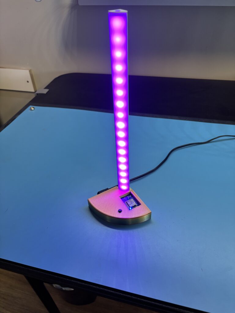
The finished project
It is a small lamp using a strip of RGB LEDs powered by a 5-volt power source. It requires some 3D printing and some simple soldering. The materials cost less than $10.00. It can be configured to many different active patterns using WLED in a browser. After the initial installation and configuration, it can be easily modified with a mobile device.
Intrigued?? Then let’s begin by following the instructions below.
Required materials
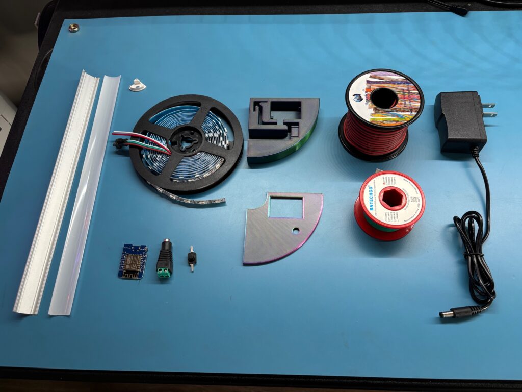
- Extruded aluminum channel kit – Amazon
- ESP8266 controller board – Amazon
- A strip of 16 RGB LEDs – Amazon – You need to cut the LED strip from the roll.
- A 3D printed enclosure – The STL files are provided in this project description.
- 22AWG multi-stranded wire, (red, black, green is suggested) – Amazon
- A 5-volt power supply – Amazon – This comes with the power plug connector below. They can be purchased separately as well.
- A power connector – Amazon – This is the connector by itself if you use some other USB power supply.
- A power switch – Amazon
If you purchase all the materials on this list, you will have much more than is needed to build a single mood lamp, but the average cost of an individual lamp should still be less than $10.00. Perhaps you and your STEM group could all do these together.
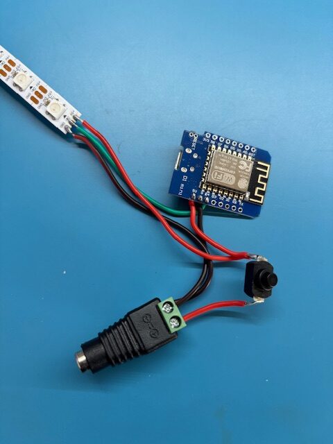
Step 1. Build the wiring HARNESS
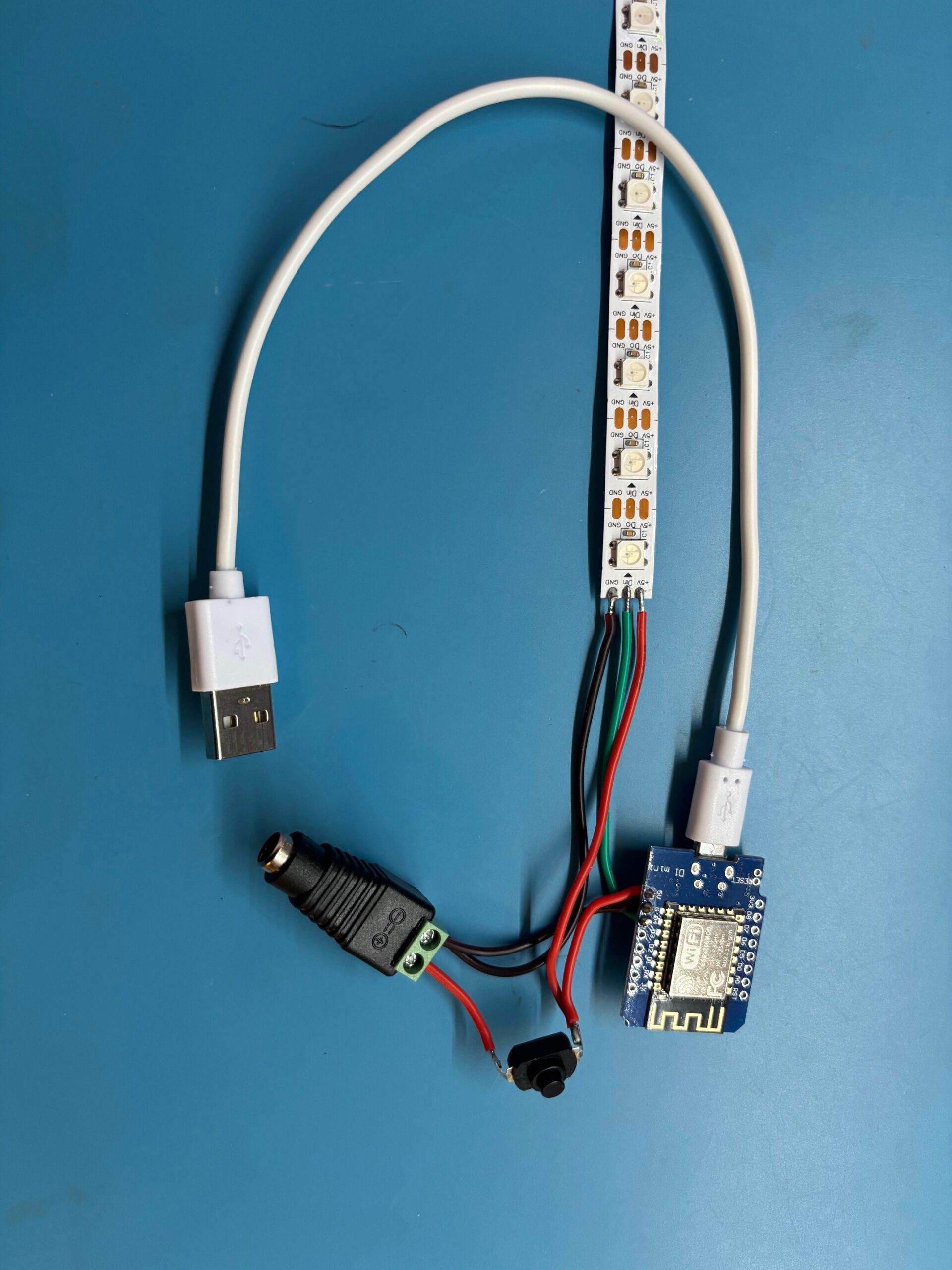
Here’s where you will need to do some soldering. Your finished harness should look like the photo on the left. The red wires carry the 5-volt power from the power connector, through the power switch to the controller board and to the LED strip. The black wires are the ground return from the controller and the LED strip. The green wire carries the control signal from the controller board to all the LEDs in the strip. This photo and the schematic below should give you all the information you need to succeed with this step.
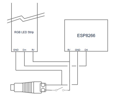
the schematic of the wiring Harness
This schematic should be helpful for doing the building of the wiring harness. The wiring harness needs to fit inside the 3D printed lamp case. Thus, the wire lengths need to be fairly precise. I have included a list of wire lengths below.
- Red wire, 1.2 inches. This goes from the power connector to the power switch.
- Red wire, 1.6 inches. This goes from the right side of the power switch to the 5v input of the ESP8266 controller.
- Red wire, 3.6 inches. This goes from the right side of the power switch to the 5v input on the RGB LED Strip. You should now see why the power switch has a single red wire on one side and two red wires on the other side, shown in the photo of the wiring harness above.
- Black wire, 2.1 inches. This goes from the ground side of the power connector to the GND pin of the ESP8266.
- Black wire, 4.0 inches. This goes from the ground side of the power connector to the GND input of the RGB LED Strip.
- Green wire, 2.75 inches. This goes from the D4 pin of the ESP8266 controller to the Din input of the RGB LED Strip.
Step 2. Programming the ESP8266 controller
Before assembling the mood lamp, you need to program the controller. For this you will need to obtain a cable with a USB-A connector on one end and a micro-USB connector on the other end, as shown in the photo at the left. Verify that the cable can transmit data as well as power from your laptop or desktop. Some cables like this are only used for charging a device and will not be able to transmit data.
Steps to program the controller
- Plug in the cable to a USB socket in your computer and open a browser tab to Install WLED. You will see an interface that will have a few steps for doing the installation. Your LED strip will probably have all the LEDs lit to a default color.
- If you have trouble getting the interface to recognize your controller on a COM port, try holding the reset button on the controller in its “pushed” position. While holding the button down, plug in the USB cable. Then release the reset button. When the interface sees your device, a window will open, and you can select your device with a mouse click. Then click “Connect”. Now you will see a new window with the title “Device Dashboard”. Click on “Install WLED”. Next you will see a window entitled “Confirm Installation”. Click on “INSTALL”. The installation will take a few minutes.
- At completion of the installation of WLED, a new window will indicate “Installation complete”. Click “NEXT”.
- A new window entitled “Configure Wi-Fi” will appear. Choose your desired network name and enter the password for that network. Click “CONNECT”. After connecting, click on “VISIT DEVICE”.
- Congratulations! You have succeeded in installing WLED on your controller board and your browser tab is connected directly to the web server contained in the WLED application on your controller board. Now, the real fun begins!! But before you forget, write down the IP address shown at the top of your browser window. It should look something like this: 192.168.0.91 We’ll discuss why you need this later.
Step 3. Configure your presets
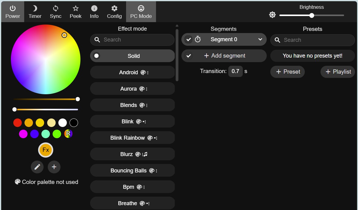
This interface takes a while to get acquainted with. It’s all about making your LEDs blink in pleasing patterns. You may configure as many patterns as you want and save them as presets that your controller will remember. Now let’s talk about the various columns in the interface.
The column on the left is the color palette designer. It allows you to construct a palette that will be used in the second column of controls, which is entitled “Effect mode”. There are dozens of these modes that have been predefined for you, and they are all named in the buttons in this column. If the effect mode name on a button contains a palette symbol, the effect will use the palette currently configured in the left column.
Thus, you can select an effect mode button in the second column. The effect will immediately be visible on your LED strip. You can then modify the effect by either changing the colors in the palette or by using the slider controls at the bottom of the second column. These slider controls will vary depending upon the effect chosen. There is also a brightness slider in the top right corner.
Trust me. You can spend hours fiddling with all these effects. When you find an effect that you really like, you may preserve all the current settings in a preset. Click on the “+ Preset” button at the bottom of the right column. Check the preset options desired and click “Save”. You will then see this new preset in your list in the right column. In this manner, you can create a preset list as big as you want.
Step 4. Final configuration
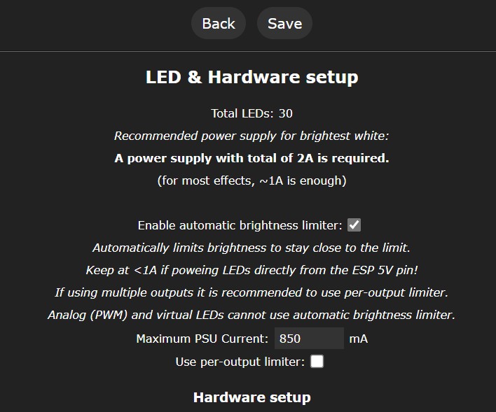
After you have a list of presets, you need to click on the “Config” button in the top left row of command symbols. This takes you to a new stack of menu choices. Choose the one that says, “LED Preferences”. This choice brings up the “LED & Hardware setup” page shown on the left. There are many options here, but only 2 are important at this time.
- Scroll down to the place where you see the line with the following: Start __ Length __
- Leave the default “Start” value at 0 but enter the number of LEDs in your LED strip in the “Length” field. I cut my strips to have 16 LEDs, but there is room for 17 if you desire to max out the strip length. Whatever number you decide on is what you enter into this hardware setup field.
- Scroll down farther to the defaults section and find the line: “Apply preset __ at boot”
- Enter the number of the preset you want to be in effect when the lamp is first turned on.
- There are other defaults you may want to change, but I haven’t tried any others in any of my lamp projects. The last thing to do is click “Save” at the top of the page and “BACK” in the menu stack. Now you are back to the original configuration menu. You should now see that there is a star next to your choice of which preset your lamp will use at power up. Congratulations, you have finished all the installation and configuration steps for your lamp controller.
Step 5. Produce the 3D prints
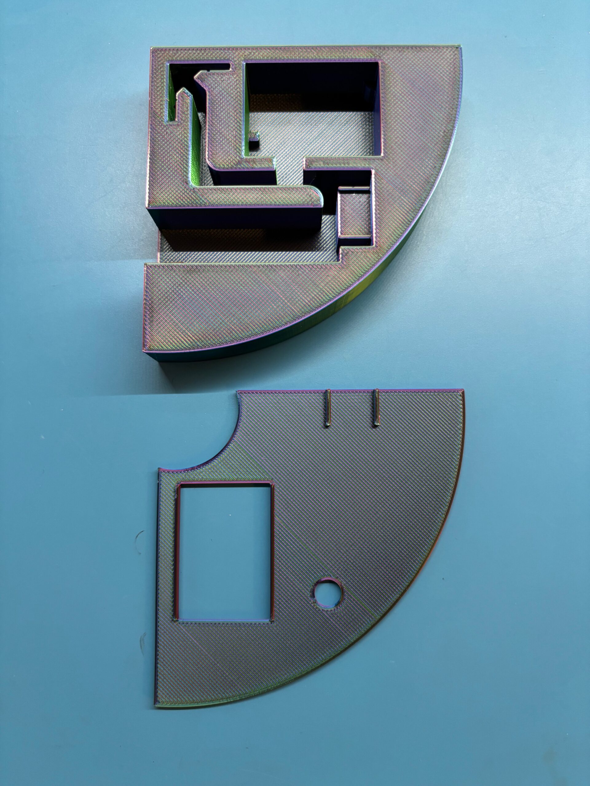
Perhaps it would have been better to place this step at the beginning of the list of instructions so that you would have the prints at this point when you need them in the assembly process. I hope you are one of the rare individuals who reads all the instructions of a project before beginning. You can obtain the two STL files for this project from my Thingiverse account at this link. When finished printing you should have two pieces, the case body and the case top plate, as shown in the photo on the left.
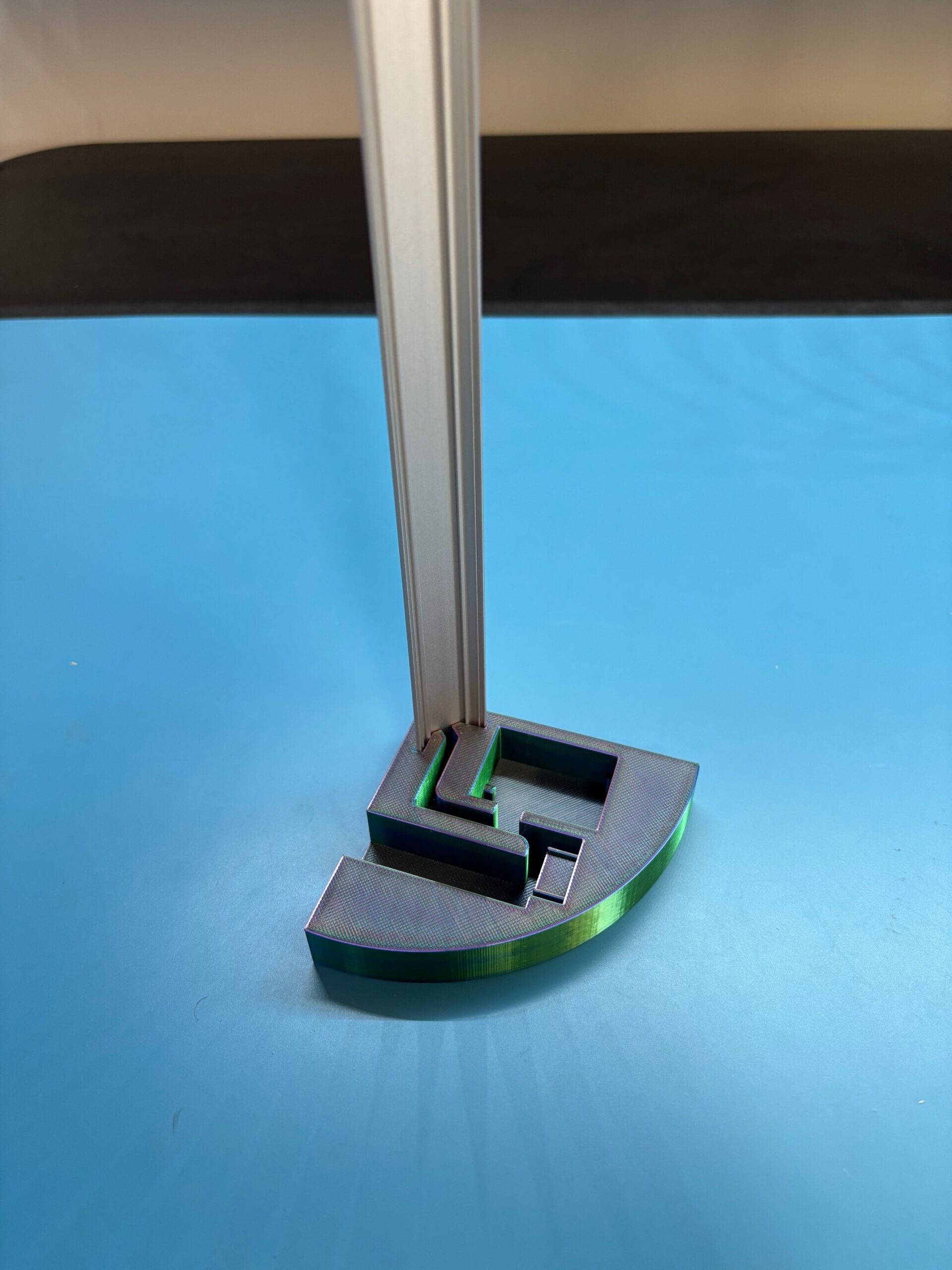
Step 6. install the aluminum channel
Now you will insert the aluminum channel into the case body. This step is simple, but a bit tricky. I like to put the case body on a sturdy flat surface and manually start the insertion by pressing the channel down into its slot in the corner of the case body. Don’t try to get the channel inserted all the way down by pure muscle power, like Superman might do. Just get it started and straight, then use a dead-blow hammer or a rubber mallet to tap the channel all the way down as far as it will go. When finished, your lamp will look like the picture on the left.
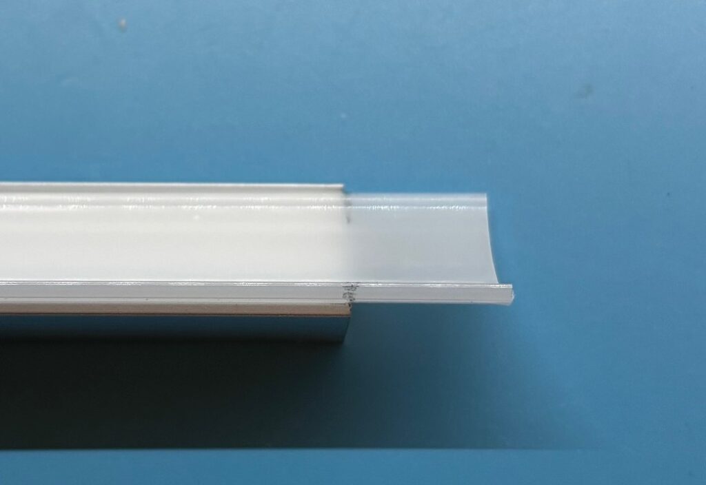
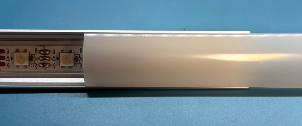
Step 7. Trim the diffuser strip
Because you have inserted the aluminum channel into the case body, the diffuser strip is now too long for the part of the channel that protrudes out of the case body. Therefore, it must be trimmed. Lay the case and channel assembly down horizontally. Then place the diffuser strip on top of the channel, with one end contacting the case, as shown in the photo on the top left. Make a mark on both sides of the diffuser strip as shown so you will know how much needs to be trimmed off.
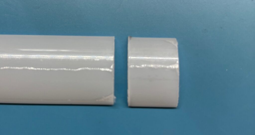
A sturdy pair of scissors or perhaps some tin snips will do the job nicely. When you are done with this step you should have trimmed the diffuser strip by how much was inserted into the case as shown in the photo on the bottom left. When you are done with the cutting, you can remove the protective film from the diffuser strip.
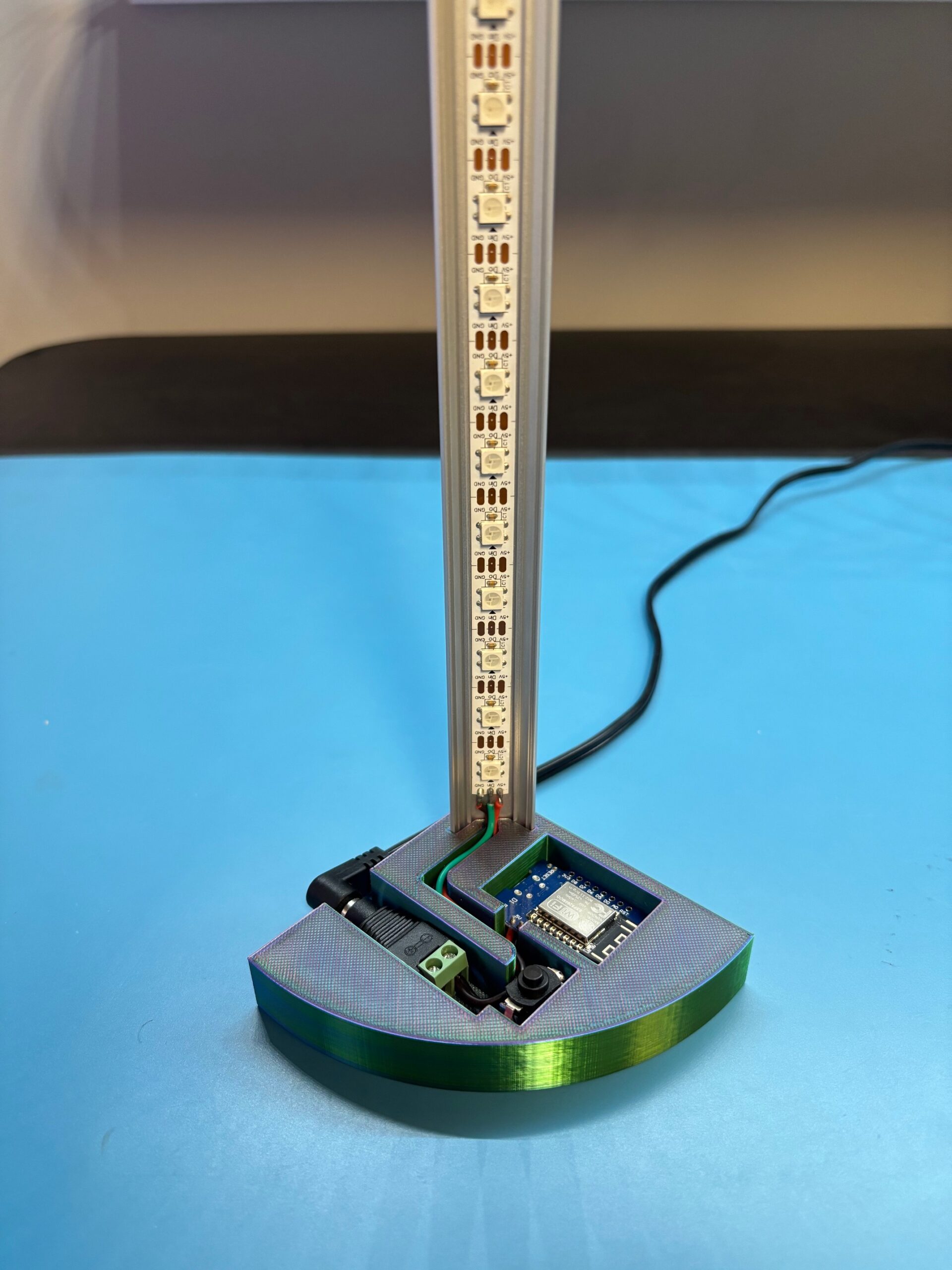
Step 8. Install the wiring HARNESS
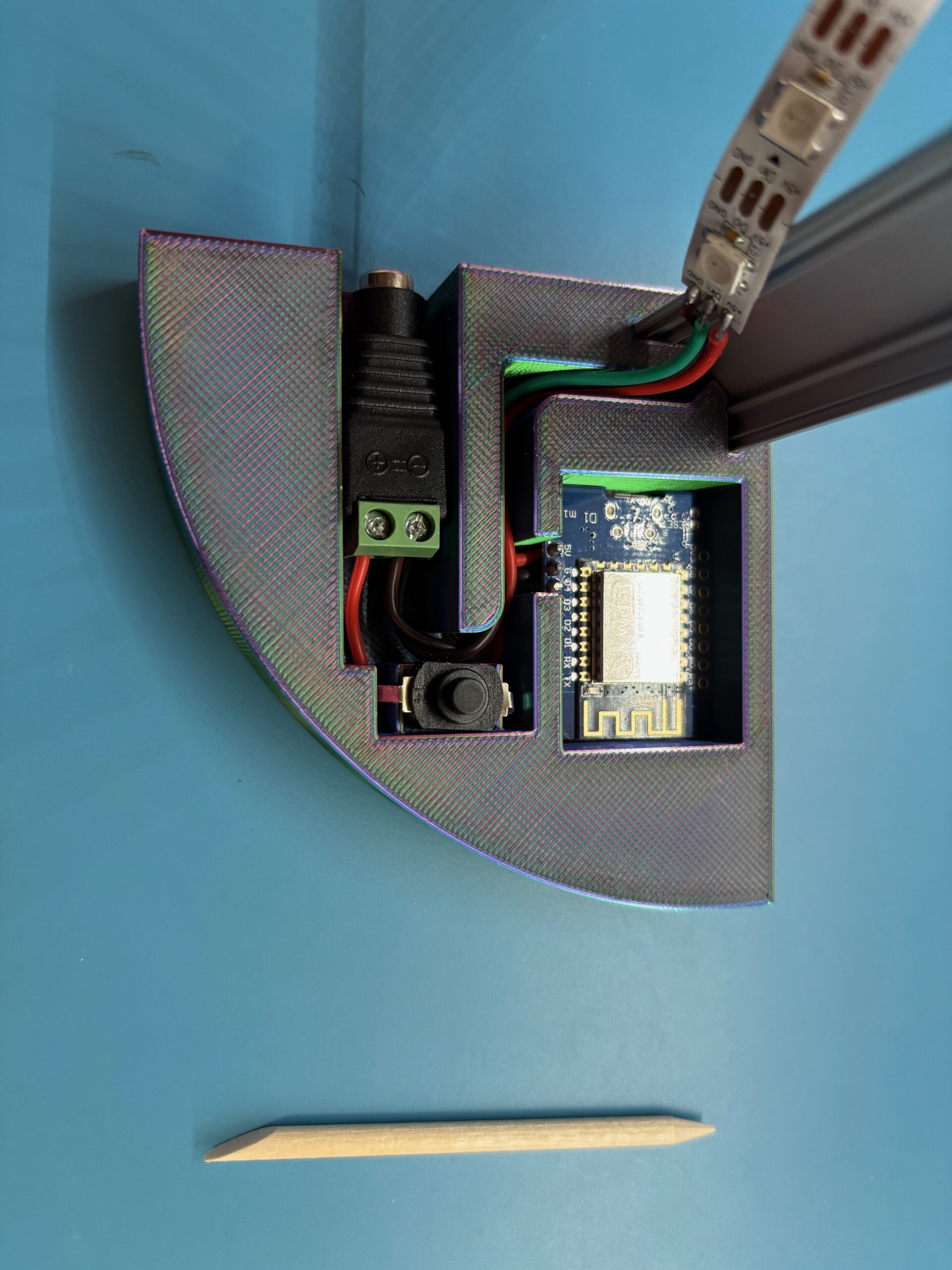
You are now ready to install the wiring harness into the case body. Start with the power connector plug. The width of these connectors seems to vary a bit. It should fit very snugly into the connector slot, but if it is loose and able to slide in the slot, you would be wise to lift up the end where the power adapter plugs into the connector and use some kind of glue under the connector. Hot glue will work fine. After applying the glue, press the connector firmly down until the entire connector is below the top edge of the slot.
Now work the wires until they fit into the case body slots, as shown. The power button should rest fully down in its cradle and the other wires should be near the bottom of the slots. I find that a popsicle stick, or a wooden manicure stick, as in the photo, or even a table knife is useful for tucking the wires fully down into their slots. The controller board should fit into its cavity and rest on the small supports. The LED strip still has the cover over the adhesive on the back and has not yet been attached to the aluminum channel, as shown in the photo.
Step 9. Attach the led strip to the channel
It is now time to remove the cover over the adhesive on the back of the LED strip. Start peeling the cover off the LED strip at the free end that has no wires soldered to it. Then start at the bottom, where the wires are, and press the sticky side against the flat bed in the middle of the aluminum channel. If all went well, your mood lamp should now look like the photo.
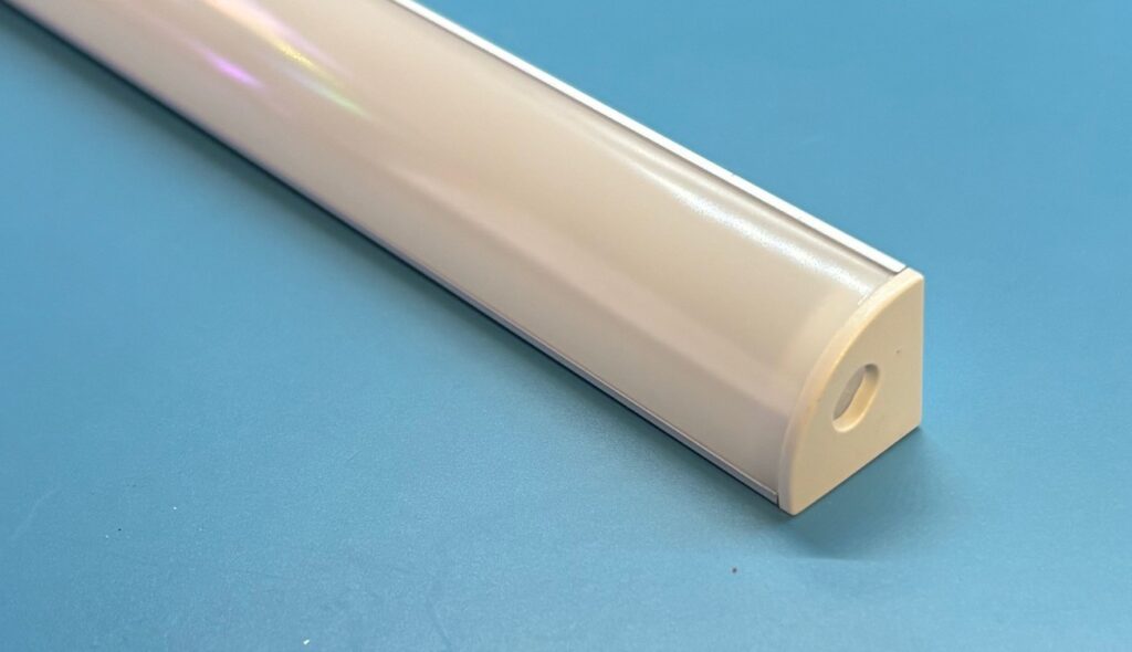
Step 10. Final assembly
The last two things to put in place are the diffuser strip and the channel cap. The diffuser strip is a little tricky to convince to slide onto the aluminum channel. You must squeeze the diffuser at one end, causing the curved strip to have a curve that is narrower, so it fits into the channel slots at the top end of the channel, as shown on the left. Now, squeeze and push the diffuser in small increments until it is fully in place. Now, attach the channel cap with a little gentle pressure. Finally, snap the top plate onto the base body. It should snap into place and remain tightly attached. Your assembly is now complete.
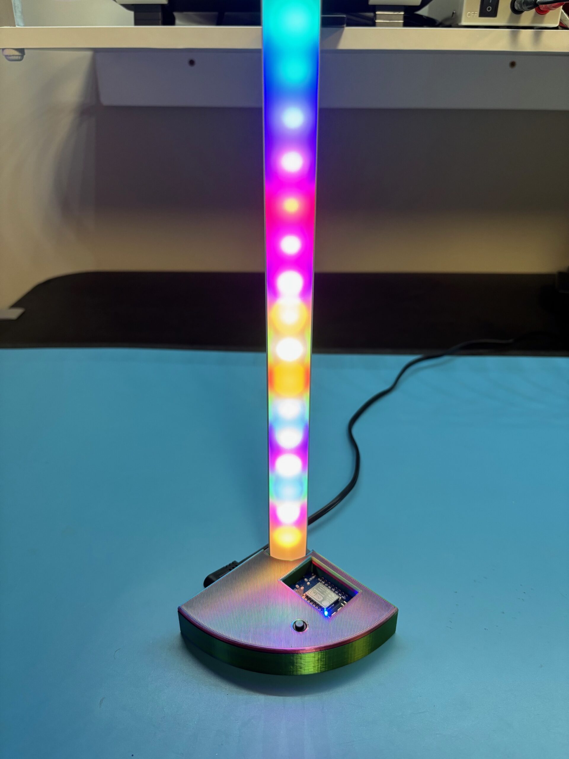
Step 10. Test and enjoy
Your beautiful new mood lamp is now finished and looks like a work of techno-art. After plugging in the power adapter cord, and pushing the power button, you should see the LEDs flashing in the pattern you chose to be the power up preset.
If you ever want to change to a new preset, you should be able to use your laptop or any mobile device with a browser to connect with the control board and see the same interface you used to configure your presets earlier. You must be near your router so the mood lamp can detect your Wi-Fi signal in the same network that was used originally.
Then, in the URL address field of a browser tab, type in the numeric IP address that you recorded when you connected manually with a USB cable. (It should look something like this: 192.168.0.91) As long as your router doesn’t reassign your mood lamp to a new network IP address, you should be able to talk to your lamp as often as you like to change the power-up preset or create new presets.